
Transformation matrix from D-H Parameters
This tool helps in calculating Transformation matrices often required when working on Serial Robots for kinematics, control, and dynamics. It uses the most common method of representing joints and links — DH parameters. Follow the steps below to use it for your application.
Step 1: Define Z Axis
Choose z_i along the axis of motion of the (i+1)th link.
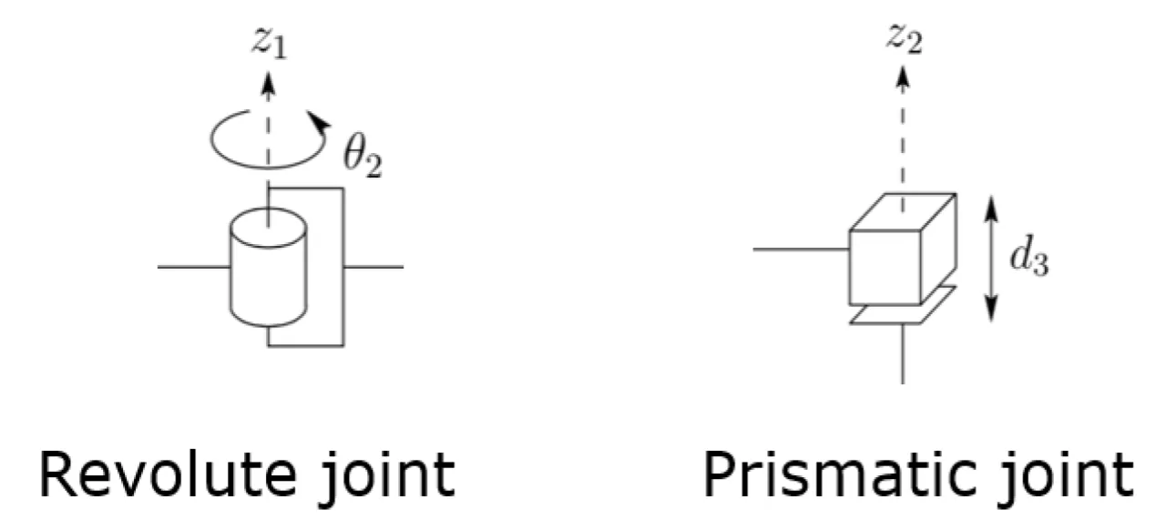 Step 1: Define Z Axis
Go along all the joints in the robot and define the Z axis for each joint as shown above.
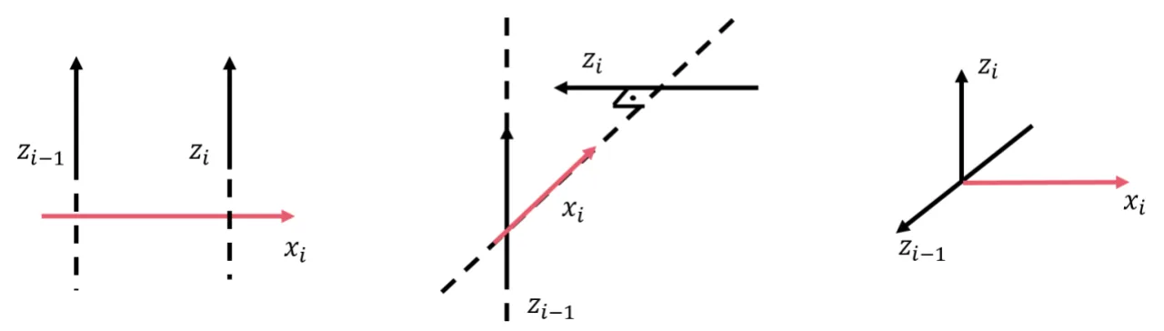
Step 2: Define X Axis
Choose x_i such that it is the shortest vector between z_(i-1) and z_i.
Step 3: Get D-H Parameters
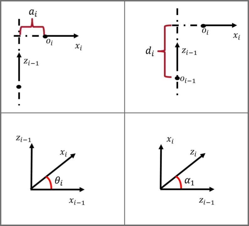 Step 3: Get D-H Parameters
Now enter the 4 DH parameters for each joint:
- a_i — the distance between z_(i-1) and x_i along the direction of x_i
- alpha_i — the angle between z_(i-1) and z_i along x_i (in degrees)
- d_i — the distance between z_(i-1) and x_i along the direction of z_(i-1)
- theta_i — the angle between x_(i-1) and x_i along z_(i-1) (in degrees)
Note: units of a and d must be the same.
Step 4: Calculate
Enter your robot’s DH parameters below. Click Load ABB IRB120 demo to see a worked example with the ABB IRB120 6-DOF arm.
D-H Parameter Calculator
| # | a | α (°) | d | θ (°) | |
|---|---|---|---|---|---|
| 1 |
Individual matrices
Combined — T = T₁ · T₂ · … · Tn
Demo: ABB IRB120
The calculator includes a built-in example using the ABB IRB120 6-DOF industrial arm. The images below show the robot, its DH frame assignments, and the parameter table used in the demo.
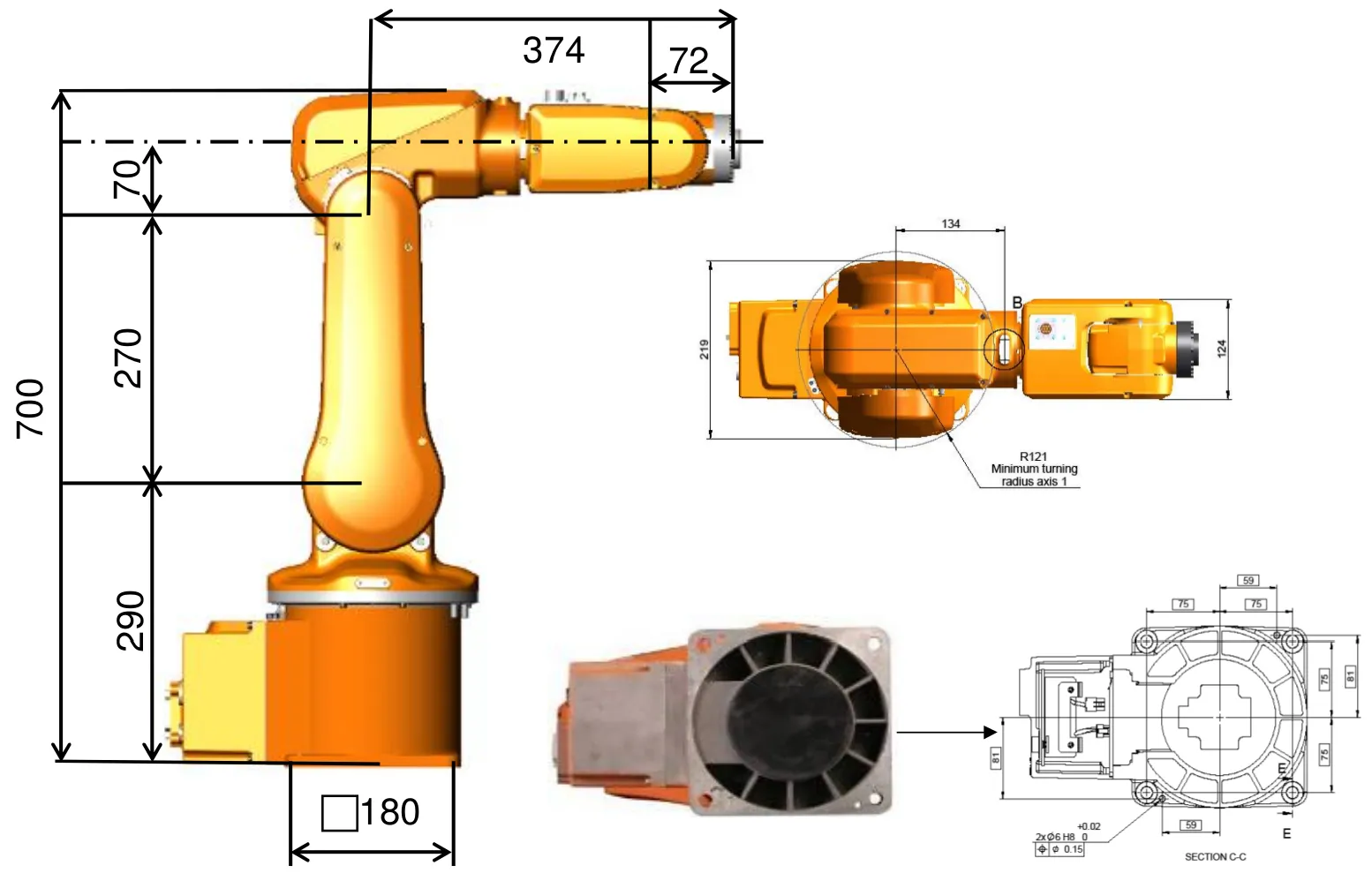
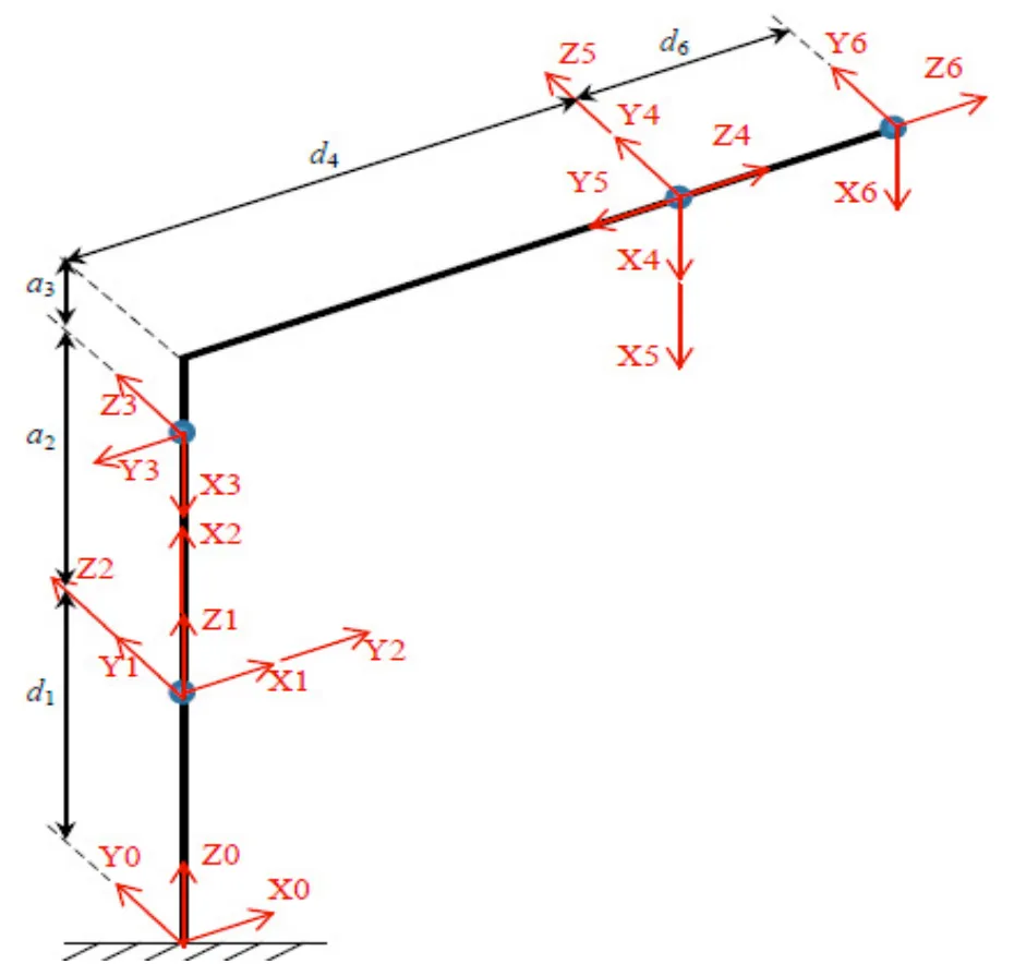
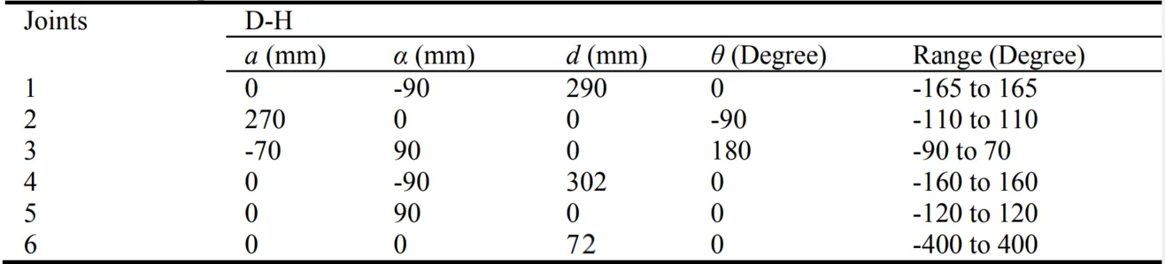 IRB120 DH parameters — robot images are courtesy of abb.com and used here as reference only.